
Latest Products


Contact Us
- 2F. No.216-2, Zhongzheng Rd., Shulin Dist., New Taipei City 238, Taiwan
- fong.yong01@msa.hinet.net
- +886-2-26824939
Epoxy Potting Compound — UL94 V-0, Two-Stage Cure, HDT 130°C | E536 / H536
E536/H536 is a flame-retardant 2-part epoxy potting compound designed for rigid encapsulation, thick-section stability, and long pot life processing. Made-to-order supply from Taiwan.E536/H536 is a UL94 V-0 epoxy potting compound for thick-section potting where single-stage cure causes internal cracking. Two-stage profile (80°C + 120°C). RTI 130°C, HDT 130°C, Tg 117.8°C by TMA. UL File E120665, min. thickness 1.58 mm.
Description
Fong Yong Chemical Co., Ltd. is one of the leading manufacturers and suppliers of Epoxy Potting Compound — UL94 V-0, Two-Stage Cure, HDT 130°C | E536 / H536 in Taiwan. Welcome to wholesale bulk customized Epoxy Potting Compound — UL94 V-0, Two-Stage Cure, HDT 130°C | E536 / H536 at low price from our factory. If you have any enquiry about quotation and free sample, please feel free to email us.
Short answer: delayed cracking in thick epoxy potting is driven by cure-induced residual stress from uncontrolled exotherm during curing.
In thick-section epoxy potting, failure is rarely caused by insufficient material strength at the time of production. It is more often caused by how the material cures, how heat accumulates inside the poured mass, and how residual stress is locked into the part before the assembly ever enters service.
E536/H536 is a two-component, flame-retardant epoxy potting compound designed for thick-section mass potting applications where the dominant failure mode is internal cracking caused by curing stress. Its two-stage cure profile - 80°C × 2 hours followed by 120°C × 4 hours - is not a default cure schedule but an engineering requirement: the first stage initiates cross-linking at a temperature low enough to limit the exothermic temperature rise within the potted section, while the second stage drives the system to full cure at Tg 117.8°C (measured by TMA per ASTM E831).
E536/H536 achieves the highest UL Relative Thermal Index in this product group - 130°C for Electrical, Mechanical Impacted, and Mechanical Strength properties under UL File E120665. It is also certified at the thinnest minimum thickness in the group: 1.58–1.74 mm (black colorway). Its HDT of 130°C and Shore D of 89 define a rigid, thermally stable encapsulant for assemblies that must maintain dimensional form at elevated continuous operating temperatures.
Delayed cracking in a thick-section epoxy potting is almost never a material defect - it is a cure process defect. The crack forms weeks or months after the assembly ships because the residual stress from a single-stage high-temperature cure accumulates with cyclic thermal stress until it exceeds the tensile strength at a geometric concentration. E536/H536's two-stage profile addresses the origin of that residual stress at the point where it is set: during cure.
Key Takeaways for Engineering Evaluation
Two-stage cure is mandatory, not optional - single-stage high-temperature cure of thick sections generates uncontrolled exotherm in the core, producing residual tensile stress that causes delayed cracking during subsequent thermal cycling; the 80°C first stage is specifically designed to limit this effect.
RTI 130°C - highest in this product group - certified under UL File E120665; suitable for assemblies that operate at continuous temperatures where E532/H532 (RTI 90°C) would be outside its rated insulation life.
CTE characterized by TMA testing - α1 = 49.772 ppm/°C (below Tg), α2 = 148.482 ppm/°C (above Tg), Tg = 117.8°C (ASTM E831); these values enable quantitative interface stress analysis for component-to-potting CTE budget calculations.
Minimum UL thickness 1.58 mm - the thinnest certified cross-section in this group; designs constrained to thin potting sections can achieve V-0 classification where other products in this group require 5–7 mm.
Low initial viscosity facilitates heated dispensing - mixed viscosity of 350–650 cps at 60°C allows good fill without vacuum in less complex geometries; viscosity is tunable by adjusting dispensing temperature.
Field note: The two-stage cure requirement is straightforward in controlled production, but the risk point in practice is the oven transition between Stage 1 and Stage 2 - specifically, whether the assembly actually reaches 80°C throughout the cross-section before the temperature is raised, or whether the oven control moves to 120°C while the core of a thick section is still warming. For thick poured sections, validate actual core temperature (with embedded thermocouple) during the Stage 1 hold before finalizing the production oven profile.
When to Use E536/H536
- Thick-section mass potting - typically >5 mm - where a single-stage cure epoxy would generate sufficient internal exotherm to cause core temperature overshoot, producing residual stress and delayed cracking.
- Designs requiring HDT ≥ 130°C to maintain dimensional stability when the potted assembly operates at sustained elevated temperature, such as in motor control modules, inverters, or high-ambient industrial equipment.
- Applications requiring RTI 130°C as the continuous insulation temperature rating - the highest available in this product group, and appropriate where IEC or UL end-product standards specify a material thermal class at or below 130°C.
- Designs where the potting thickness is constrained below 5 mm and UL 94 V-0 is required - E536/H536 achieves V-0 at 1.58 mm, while other products in this group require 5–7 mm.
- Engineering teams performing CTE budget analysis for component-to-potting interface design - E536/H536 is the only product in this group with characterized CTE data (α1, α2) from TMA testing, enabling quantitative stress estimation at the interface.
- Production environments capable of heated dispensing (40–60°C) where viscosity reduction improves fill efficiency without compromising gel time control.
When NOT to Use E536/H536
- Applications requiring room-temperature cure. E536/H536 must be heat-cured (minimum 80°C first stage); RT cure is not a qualified option. Productions requiring ambient cure flexibility should use E532/H532.
- Designs where thermal conductivity is the primary selection criterion. At 0.5 W/m·K, E536/H536 does not provide meaningful conductive heat removal. If the potting compound must carry heat from a power-dissipating component to a cooling surface, E533/H533 at 1.5 W/m·K is the appropriate product.
- Assemblies subject to mechanical vibration or shock where the potting must absorb deformation energy. Shore D 89 and the absence of a flexible formulation mean E536/H536 transfers mechanical stress to embedded components rather than absorbing it. If vibration-induced component failure is a concern, a lower-modulus alternative should be evaluated.
- Potting sections using colors other than black where UL certification at the minimum tested thickness is required. The UL certification at 1.58–1.74 mm applies specifically to the black (BK) colorway. Other colors are not covered by the current UL listing at this minimum thickness.
- Designs that cannot execute a two-stage cure profile. Oven control capable of the 80°C and 120°C stages with appropriate hold times is required. A single-temperature cure cycle is not a validated substitute for thick sections.
- Engineering note: If production cannot reliably execute the two-stage cure profile with controlled transition from 80°C to 120°C, selecting E536/H536 does not reduce cracking risk by itself. The material assumes the cure process is executed correctly; when the cure profile is shortened, skipped, or treated as interchangeable with a single-temperature cycle, the same residual-stress failure mechanism can still be built into the assembly.
Failure Scenario: What Happens When Curing Stress Is Not Controlled
Short answer: cracking in thick epoxy potting is driven by cure-induced stress, not by mechanical overload.

Figure 1. Cracking may develop in thick-section epoxy potting when curing-induced stress is not properly managed, while a stable process maintains a smooth and uniform surface.
In a thick-section epoxy potting application - for example, a transformer core assembly with a 20 mm poured section - a single-stage cure at 120°C initiates the exothermic cross-linking reaction too aggressively across the mass. The outer surface, in contact with the oven atmosphere, remains closer to the oven setpoint. The core, insulated by the surrounding resin, can reach a higher temperature because reaction heat cannot dissipate at the same rate. Core temperatures above the oven setpoint are possible in large poured sections, even when the oven is controlled correctly.
If the cure profile allows uncontrolled exotherm, internal stress is already designed into the part before it ever enters service. The core and outer layers do not cross-link, shrink, and cool under the same thermal history. As the assembly cools, the already-cured region resists deformation while other regions continue to contract. This creates locked-in residual tensile stress around corners, embedded components, housing interfaces, and other geometric concentration points.
The characteristic failure signature is delayed cracking. The assembly may pass initial electrical and visual inspection, but cracks or interface delamination appear after thermal cycling, vibration, or sustained elevated-temperature operation. Because the failure occurs after shipment, it is often investigated as material fatigue, component movement, or adhesion loss. In practice, the original cure process is frequently under-documented: production records may show oven setpoint and total time, but not core temperature, Stage 1 dwell confirmation, or the actual transition timing between 80°C and 120°C.
E536/H536 addresses this failure mode by separating the cure into two functional stages. The 80°C first stage initiates cross-linking at a controlled rate to limit the core-to-surface temperature differential during the most sensitive reaction window. The 120°C second stage then drives the system to full cure, supporting the specified Tg, HDT, and dimensional stability. The two-stage profile does not make the epoxy flexible; it reduces the residual stress created during cure so the rigid cured mass is less likely to crack during later thermal cycling.
This is why E536/H536 should be evaluated as a cure-stress control material, not simply as a high-strength or high-temperature epoxy. If cracking is caused by vibration, component movement, poor adhesion preparation, or excessive CTE mismatch beyond the validated geometry, material selection alone may not solve the issue. The cure profile, section thickness, housing geometry, and interface design must be validated together before production release.
Application Process
The curing behavior of thick-section epoxy systems is not a single-step transition, but a controlled evolution from liquid flow to partial stabilization and finally to a fully crosslinked solid.

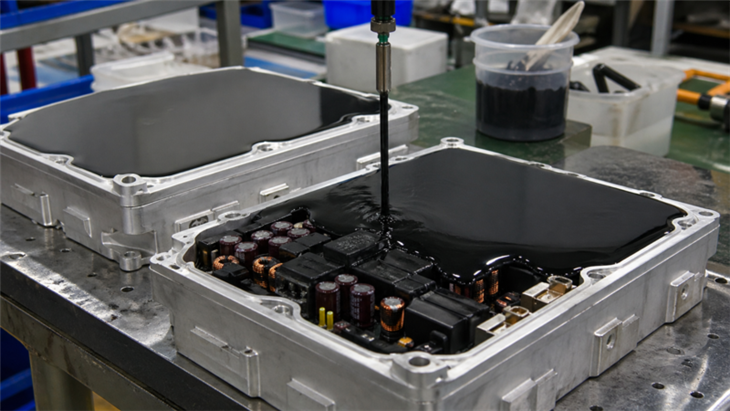
Figure 2. Three-stage epoxy potting process showing material transition from liquid filling, early-stage curing (partial stabilization), to fully cured solid state. Surface behavior evolution illustrates process control requirements in thick-section encapsulation.
- Base component pre-mixing
Stir the E536 resin in its container before weighing. E536 is a black liquid; verify uniform color and consistency throughout before use. Additive settling in storage produces a non-homogeneous base, resulting in property variation between the top and bottom of the container across a production run.
- Ratio weighing - 100 : 30 by weight
Weigh E536 and H536 at a 100 : 30 ratio. The hardener fraction (23% of total mass) is larger than E532/H532 or E533/H533, so absolute weighing error has a smaller relative effect - but stoichiometric deviation from 100:30 shifts cross-link density and directly affects Tg and HDT. Failure risk if ratio is wrong: reduced HDT (under-hardener) or increased brittleness (over-hardener), both of which alter the cracking resistance profile that is the primary reason for selecting this product.
- Temperature-controlled mixing - select by geometry
Mixed viscosity at 25°C is 1,700–2,200 cps - suitable for open cavity dispensing. For narrow fill channels, raising to 40°C (650–950 cps) or 60°C (350–650 cps) improves void-free fill. Voids act as stress concentrators; in a system specifically designed to manage curing stress, geometric stress concentrators from voids directly undermine the purpose of the controlled cure profile. Scrape container edges and base during mixing.
- Dispensing within pot life
Apply within the 24-hour pot life at 25°C. For heated dispensing, validate working time at the actual dispensing temperature - viscosity reduction shortens pot life. Fill from the lowest cavity point and allow material to self-level. Vacuum degassing is recommended for geometries with re-entrant features or buried components.
- Stage 1 cure: 80°C × 2 hours
Place the filled assembly in an oven pre-set to 80°C. Hold for 2 hours. At 80°C, cross-linking initiates throughout the mass at a controlled rate - the exothermic heat generation is low enough that core temperature overshoot is limited. The cross-link network develops at roughly uniform density across the cross-section.
** Critical: Do not skip or shorten Stage 1. Premature transition to 120°C before initial cross-linking is established replicates the single-stage failure mode: core exotherm spike → core-to-surface Tg gradient → residual tensile stress → delayed cracking during thermal cycling. This failure appears after 50–200 cycles, not at first test.**
- Stage 2 cure: 120°C × 4 hours
Without removing the assembly, raise oven temperature to 120°C and hold for 4 hours. Stage 1 alone does not drive cross-linking to completion - full Tg (117.8°C by TMA) and HDT 130°C require Stage 2. Stopping after Stage 1 yields an under-cured system. Verification: cure witness specimens simultaneously with production parts and check HDT; a value substantially below 130°C indicates incomplete Stage 2.
- Controlled cool-down
After Stage 2, allow the assembly to cool to below 60°C inside the oven before removing to ambient. CTE above Tg (α2 = 148.482 ppm/°C) is approximately 3× the below-Tg value (α1 = 49.772 ppm/°C). Rapid removal from 120°C generates additional thermal gradient stress at the potting-substrate interface - a separate, avoidable stress source that reduces the benefit of the two-stage cure.
Supply & Procurement Information
Mix ratio: 100 : 30 by weight (E536 : H536)
Pot life: 24 hours at 25°C; shorter at elevated dispensing temperature - validate at production conditions
Shelf life: Store at <25°C in sealed containers; consult TDS for detailed shelf life; keep E536 and H536 containers segregated to prevent cross-contamination
Storage: Cool, dry location below 25°C, away from direct sunlight, heat, and humidity; avoid freezing
Packaging: Contact Fong Yong for available pack sizes and minimum order quantities
Documentation available: Technical Data Sheet (TDS), UL Certificate of Compliance (File E120665), Tg and CLTE test report (TMA, ASTM E831/D3386, tested by Fong Yong factory, September 2022)
Lead time: Contact Fong Yong for current availability and recommended safety stock for your production volume
Next Steps
FAQ
Q: Why is the two-stage cure necessary instead of a single 120°C cure?
A: Short answer: the cure profile controls residual stress, not just cure completion. In a single-stage 120°C cure of a thick section, the reaction can generate heat faster in the core than the surrounding resin can dissipate it. The core and surface then cure under different thermal histories, which locks residual stress into the potted mass. The two-stage cure (80°C × 2 hours → 120°C × 4 hours) reduces this temperature gradient during early cross-linking before completing the cure at the higher temperature. If delayed cracking appears after thermal cycling, the cure profile should be reviewed before assuming the material itself is defective.
Q: The TMA report gives Tg at 117.8°C but the TDS states HDT at 130°C. Why are these different?
A: These values measure different physical phenomena. Tg (glass transition temperature) measured by TMA is the inflection point where the polymer network transitions from glassy to rubbery behavior - it reflects the degree of cross-linking achieved. HDT (Heat Deflection Temperature, sometimes called HDT under 1.8 MPa load per ISO 75-2) measures the temperature at which a standard specimen deflects a specified amount under a fixed mechanical load - it depends on both Tg and the stiffness of the material at elevated temperature. HDT is often numerically higher than TMA Tg for highly cross-linked, highly filled systems because the material remains stiff enough at Tg to support the load condition. For component selection, use Tg (117.8°C) as the limit for dimensional stability and CTE analysis; use HDT (130°C) as the limit for mechanical load-bearing at elevated temperature. Neither should be used as the continuous operating temperature limit without a thermal derating margin.
Q: What is the significance of the two CTE values (α1 and α2)?
A: α1 = 49.772 ppm/°C is the coefficient of linear thermal expansion measured below Tg (from approximately 30°C to 80°C by TMA). α2 = 148.482 ppm/°C is the value above Tg (from approximately 135°C to 144°C). The approximately 3× difference between the two values is characteristic of glassy-to-rubbery polymer transitions. For interface stress analysis - for example, assessing whether the CTE mismatch between E536/H536 (α1 ~50 ppm/°C) and a copper lead frame (~17 ppm/°C) will generate delamination over a thermal cycle from -40°C to +85°C - use α1, since the operating range stays below Tg. If the design requires operation through Tg during cure or soldering, both values are needed for the full stress cycle calculation. The test was performed per ASTM E831 and ASTM D3386 using TMA on specimens cured at the standard 100:30 mix ratio and the full two-stage cure schedule.
Q: The minimum UL certified thickness is 1.58–1.74 mm. Does this apply to all colors?
A: No. The 1.58–1.74 mm minimum thickness certification under UL File E120665 applies specifically to the black (BK) colorway of E536/H536. Other colorways may be listed under different minimum thicknesses or may not be listed at all at this thickness range - consult the UL Product iQ page for E536/H536 and the current certificate of compliance before specifying a non-black variant in a UL-listed product. If your design requires a color other than black with a thin cross-section, additional UL testing at the required color and thickness may be necessary.
Stage 1 at 80°C is already a reduced-temperature first exposure compared to single-stage cures. Lowering Stage 1 below 80°C risks insufficient initial cross-linking to control the Stage 2 exotherm, which defeats the purpose of the staged profile. Components that cannot survive 80°C should be redesigned out or potted in a separate operation after heat-sensitive parts are installed - sub-80°C cure of E536/H536 will produce a part with HDT and Tg below specification.
Quick Engineering Questions
Q: Why does epoxy crack after curing in thick sections?
A: Cracking is typically caused by internal stress generated during curing. When heat builds up unevenly, shrinkage differences create stress that may exceed material limits, especially in thick-section potting.
Q: Does slower curing reduce cracking risk?
A: Slower curing may reduce thermal gradients, but it does not eliminate stress. Both material behavior and process control must be evaluated together.
Q: When should a two-stage curing system be considered?
A: Two-stage curing is typically used when part thickness or thermal mass makes single-stage curing difficult to control. It helps reduce internal stress and improve curing uniformity.
Hot Tags: Epoxy Potting Compound — UL94 V-0, Two-Stage Cure, HDT 130°C | E536 / H536, suppliers, manufacturers, factory, customized, wholesale, bulk, cheap, quotation, low price, free sample, Electrically Conductive Epoxy Adhesive, Electrically Insulative Potting Epoxy Resin, Flexible Electronic Potting Epoxy Resin, High Temp Encapsulation Epoxy Resin, Non Sag Epoxy Encapsulation Glue, Single Part Thermally Conductive Epoxy Encapsulant
Technical Information
Component Properties (Before Mixing)
| Property | E536 (Resin) | H536 (Hardener) |
|---|---|---|
| Appearance | Black liquid | Amber liquid |
| Density at 25°C (g/cm³) | 1.76 | 1.20 |
| Mix Ratio (by weight) | 100 : 30 (E536 : H536) | |
| Mixed Viscosity at 25°C (cps) | 1,700 – 2,200 | |
| Mixed Viscosity at 40°C (cps) | 650 – 950 | |
| Mixed Viscosity at 60°C (cps) | 350 – 650 | |
| Pot Life at 25°C | 24 hours | |
| Cure Schedule | 80°C × 2 hrs → 120°C × 4 hrs (two-stage, mandatory) | |
* Pot life and cure conditions depend on batch mass and section thickness. The two-stage cure profile is not interchangeable with a single-stage cure at 120°C for thick sections - see workflow for engineering rationale.
Cured System Properties (Fully Cured - Two-Stage Profile)
| Property | Value | Engineering Significance |
|---|---|---|
| Hardness (Shore D) | 89 | Highest in this product group; highly rigid - does not accommodate substrate deformation |
| Shrinkage (%) | 0.2 – 0.5 | Low shrinkage supports adhesion retention at substrate interface during cure |
| Compression Strength | 17,000 psi | Suitable for mechanically loaded potting where compressive loads are present |
| Tensile Strength | 4,500 psi | Reference for cohesive strength; interface adhesion may be the limiting factor in actual assemblies |
| Thermal Conductivity | 0.5 W/m·K | Not a heat-dissipation product; use E533/H533 (1.5 W/m·K) if thermal management is the design driver |
| Dielectric Constant | 3.9 | Lower than E532 (4.8); beneficial for high-frequency isolation designs |
| Dielectric Strength | 18.5 kV/mm | Valid for void-free sections; voids reduce effective breakdown voltage |
| Volume Resistivity | 5.0 × 10¹⁵ Ω·cm | High bulk resistivity; suitable for high-voltage insulation applications |
| HDT (Heat Deflection Temperature) | 130°C | Sets the limit for load-bearing dimensional stability; use Tg (117.8°C) as the CTE transition reference |
| Flame Resistance | UL 94 V-0 | UL File E120665; min. thickness 1.58–1.74 mm (BK colorway); RTI 130°C (Elec / Mech Imp / Mech Str) - highest RTI in this product group |
Technical Documentation & Compliance
UL Certification (File E120665) - E536/H536 is listed as an Epoxy Casting Compound under UL Component Recognition: flame class V-0 at 1.58–1.74 mm minimum thickness (black colorway), RTI 130°C for Electrical, Mechanical Impacted, and Mechanical Strength properties. Certified to both ANSI/UL and IEC requirements. 👉 🔗 View UL Certification
Technical Data Sheet (TDS) - Component properties, viscosity-temperature relationship, cure schedule, handling, storage. 👉 🔗 Download TDS
Tg and CTE Test Report - Thermomechanical analysis data (Tg 117.8°C, α1 = 49.772 ppm/°C, α2 = 148.482 ppm/°C) measured per ASTM E831, D3386, D696. Issued by Fong Yong Chemical to Line Seiki Philippines, Inc., February 2026. Available on request. 👉 🔗 Request Test Report
Engineering Selection Conclusion: E536/H536 is the appropriate choice when the governing design constraints are RTI 130°C, HDT 130°C, and control of curing stress in thick cross-sections. It is the only product in this group with both a characterized CTE dataset (enabling quantitative interface stress analysis) and a two-stage cure profile specifically designed to reduce residual curing stress. Its UL certification at 1.58 mm minimum thickness extends its applicability to designs where other products in the group would require 5–7 mm to achieve V-0 classification. It does not address heat dissipation requirements (use E533/H533 for that) and does not accommodate production scheduling flexibility (use E532/H532 for that).
You Might Also Like


